Zigbee: Light switch
You can use the this Light switch sample to change the state of light sources on other devices within the same Zigbee network.
You can use it together with the Zigbee Network coordinator and the Zigbee Light bulb samples to set up a basic Zigbee network.
This sample supports the optional Sleepy End Device behavior and Multiprotocol Bluetooth LE extension. It also supports Zigbee FOTA for nRF52840, nRF5340, nRF54L10, nRF54L15 and nRF54LM20 SoCs. Additionally, as a proof of concept, it supports the optional Matter extension, which lets the same firmware start as a Zigbee end device and migrate to a Matter device after Matter commissioning. This combined Matter build also enables Touchlink initiator support, so it can commission a nearby Touchlink target without a Zigbee Coordinator on the network. See Configuration files for sample extensions for details about how to enable these variants.
Requirements
The sample supports the following development kits:
Hardware platforms |
PCA |
Board name |
Board target |
|---|---|---|---|
PCA10056 |
|
||
PCA10095 |
nrf5340dk/nrf5340/cpuapp |
||
PCA10156 |
|
||
PCA10156 |
|
||
PCA10184 |
|
You can use one or more of the development kits listed above and mix different development kits.
To test this sample, you also need to program the following samples:
The Zigbee Network coordinator sample on one separate device.
The Zigbee: Light bulb sample on one or more separate devices.
Multiprotocol Bluetooth LE extension requirements
If you enable the Multiprotocol Bluetooth LE extension, make sure you have a phone or a tablet with the nRF Toolbox application installed.
Note
The Testing instructions refer to nRF Toolbox, but you can also use similar applications, for example nRF Connect for Mobile.
Overview
The Light switch sample demonstrates the Zigbee End Device role and implements the Dimmer Switch device specification, as defined in the Zigbee Home Automation public application profile.
Once the light switch is successfully commissioned, it sends a broadcast message to find devices with the implemented Level Control and On/Off clusters. The light switch remembers the device network address from the first response. At this point, you can start using the buttons on the development kit to control the clusters on the newly found devices.
Additionally, the light switch sample powers down unused RAM sections to lower power consumption in the sleep state.
Sleepy End Device behavior
The light switch supports the Sleepy End Device behavior that enables the sleepy behavior for the end device, for a significant conservation of energy.
To enable the sleepy behavior, press Button 2 while the light switch sample is booting.
To enable the sleepy behavior, press Button 3 while the light switch sample is booting.
This is required only when device is joining the network for the first time. After restarting the device, it will boot with the sleepy behavior enabled.
Multiprotocol Bluetooth LE extension
This optional extension demonstrates dynamic concurrent switching between two protocols, Bluetooth® LE and Zigbee. It uses the Nordic UART Service (NUS) library.
When this extension is enabled, you can use:
Buttons on the light switch device to operate on the Zigbee network
Nordic UART Service to operate on the Bluetooth LE network
Both networks are independent from each other.
To support both protocols at the same time, the Zigbee stack uses the IEEE 802.15.4 radio during the inactive time of the Bluetooth LE radio (using the Timeslot API of the Multiprotocol Service Layer). Depending on the Bluetooth LE connection interval, the nRF52 development kits can spend up to 99% of the radio time on the Zigbee protocol.
Transmitting and receiving data when using this example does not break connection from any of the used radio protocols, either Bluetooth LE or Zigbee.
For more information about the multiprotocol feature, see Multiprotocol support in the nRF Connect SDK documentation.
Matter extension
This optional extension is a proof of concept of a combined Matter and Zigbee build on a single SoC.
The ZBOSS stack and OpenThread (used by Matter) share the same 802.15.4 radio, with ownership handed over at commissioning time by the :file`zigbee_matter_coexistence` library.
For Thread networking in Matter mode, the light switch acts as an OpenThread Minimal Thread Device (MTD).
It is supported only on the nrf54lm20dk/nrf54lm20a/cpuapp board target.
Protocol selection is time-separated and persisted across reboots:
On first boot, Zigbee owns the 802.15.4 radio and the device behaves as a standard Zigbee End Device (Dimmer Switch). In parallel, the Matter stack advertises for commissioning over Bluetooth LE (CHIPoBLE) for the duration configured by
CONFIG_CHIP_BLE_ADVERTISING_DURATION(60 s by default).When a Matter commissioner completes commissioning (first CASE session established while Thread is not yet attached), the coexistence layer stops the Zigbee stack, hands the radio over to OpenThread, and persists the selected protocol. From this point on, the device operates as a Matter Dimmer Switch that controls remote Matter lights through the client-side binding cluster.
On subsequent boots, if the persisted protocol is Matter, the Zigbee stack is skipped entirely and the radio goes directly to OpenThread.
A Matter factory reset wipes the Zigbee network information, resets the persisted protocol back to Zigbee, and reboots the device as a fresh, commissioning-ready Zigbee End Device.
Onboarding data (discriminator, passcode, QR code) is produced by the Matter factory data module (CONFIG_CHIP_FACTORY_DATA_BUILD) at build time.
Touchlink commissioning
The combined Matter build enables the light switch as a Touchlink initiator (CONFIG_ZIGBEE_TOUCHLINK_INITIATOR).
This lets the device commission directly with a nearby Touchlink target (for example, the Zigbee: Light bulb built with the Matter extension) and form a distributed-security Zigbee network without a Zigbee Coordinator.
Press Button 2 during normal operation to start Touchlink commissioning.
Note
Touchlink in the Zigbee R23 add-on for the nRF Connect SDK is provided as an experimental feature with basic functionality. See Touchlink for details.
Matter extension limitations
As a proof of concept, the Matter extension has the following limitations:
The 802.15.4 radio is time-shared, never concurrent: once the device is provisioned to Matter, Zigbee is torn down, and returning to Zigbee requires a Matter factory reset (which also wipes Matter storage).
The Matter extension cannot be combined with the Multiprotocol Bluetooth LE extension (
overlay-multiprotocol_ble.conf) or with the Zigbee-only FOTA build (FILE_SUFFIX=fota).The Matter shell (
CONFIG_CHIP_LIB_SHELL) and the Matter test shell are disabled to avoid option-parsing conflicts with the Zigbee shell.The memory footprint is tuned empirically for
nrf54lm20dk/nrf54lm20a/cpuapp; porting to other targets requires revisiting the libc heap, ZBOSS thread, system work queue and partition sizes used byprj_matter_fota.conf.
Configuration
See Configuring and building in the nRF Connect SDK documentation for information about how to permanently or temporarily change the configuration.
Source file setup
This sample is split into the following source files:
The
mainfile to handle initialization and light switch basic behavior.An additional
nus_cmdfile for handling NUS commands.
Configuration files for sample extensions
The sample provides predefined configuration files for optional extensions.
You can find the configuration files in the samples/light_switch directory.
Activating optional extensions
To activate the Zigbee FOTA, use the prj_fota.conf configuration file.
For example, when building from the command line, use the following command:
west build samples/light_switch -b board_target -- -DFILE_SUFFIX=fota
The FOTA variant enables MCUboot image compression. The generated Zigbee update file contains a compressed MCUboot image, and MCUboot decompresses it while applying the update. This setting reduces the update image size, but the MCUboot must run in the overwrite-only mode, so the device cannot revert to the previous image after the update is applied.
Alternatively, you can configure Zigbee FOTA manually.
Note
You can use the prj_fota.conf file only with a development kit that contains the nRF52840, nRF5340, nRF54L15 or nRF54L10 SoC.
Note
The decompression support increases the size of the MCUboot image. When adapting this FOTA configuration to a custom board or application, make sure that the MCUboot partition is large enough for the generated bootloader image. The sample keeps the primary and secondary application slots the same size; resizing the secondary slot is optional and depends on the compression ratio of your application image.
To activate the Multiprotocol Bluetooth LE extension, set EXTRA_CONF_FILE to the overlay-multiprotocol_ble.conf.
For example, when building from the command line, use the following command:
west build samples/light_switch -b board_target -- -DEXTRA_CONF_FILE='overlay-multiprotocol_ble.conf'
To activate the Matter extension, build the sample with FILE_SUFFIX=matter_fota.
This selects the prj_matter_fota.conf configuration, which enables Matter (CONFIG_CHIP), the CONFIG_ZIGBEE_MATTER_COEXISTENCE orchestration layer, and the matching static partition layout.
west build samples/light_switch -b nrf54lm20dk/nrf54lm20a/cpuapp -- -DFILE_SUFFIX=matter_fota
To produce a size-optimized release build (no logging, console or shell), add matter_fota_release.conf as an extra overlay:
west build samples/light_switch -b nrf54lm20dk/nrf54lm20a/cpuapp -- -DFILE_SUFFIX=matter_fota -DEXTRA_CONF_FILE='matter_fota_release.conf'
See Matter extension limitations for supported board targets and incompatible options.
For the board name to use instead of the board_target, see Programming board names.
See Providing CMake options in the nRF Connect SDK documentation for instructions on how to add flags to your build. For more information about configuration files in the nRF Connect SDK, see Build and configuration system in the nRF Connect SDK documentation.
Snippets
The following snippets are available:
low_power- Enables low power consumption mode for the Light Switch sample. This snippet disables serial communication, console output, enables sleepy end device behavior, and disables LED indications to minimize power consumption.To build with the low power snippet, use the following command:
west build samples/light_switch -b board_target -- --snippet=low_power
Configurable transmission power
To achieve a lower power consumption of the light switch, you can configure the transmission power using the CONFIG_LIGHT_SWITCH_CONFIGURE_TX_POWER Kconfig option.
You can select per-channel transmission power (in dBm) with the CONFIG_LIGHT_SWITCH_TX_POWER Kconfig option.
This affects to all frames sent by the device, even in the network scan phase.
Note
The CONFIG_LIGHT_SWITCH_CONFIGURE_TX_POWER Kconfig option is enabled by default and this sample’s transmission power is set to 0 dBm.
When the CONFIG_ZIGBEE_CHANNEL_SELECTION_MODE_MULTI Kconfig option is set to y, the CONFIG_ZIGBEE_APP_CB_QUEUE_LENGTH Kconfig option must be increased depending on the channel mask.
For example, in case 16 channels are active, a proper value for CONFIG_ZIGBEE_APP_CB_QUEUE_LENGTH would be 17.
Similar consideration applies to the ZB_CONFIG_IOBUF_POOL_SIZE and ZB_CONFIG_SCHEDULER_Q_SIZE values configured in the include/zb_mem_config_custom.h file.
User interface
- LED 2:
Lit and solid when the device is connected to a Zigbee network.
- LED 3:
Lit and solid when the light switch has found a light bulb to control.
- Button 0:
Turn on the light bulb connected to the network (light bulb’s LED 1). This option is available after the successful commissioning (light switch’s LED 2 turned on).
Pressing this button for a longer period of time increases the brightness of the LED 1 of the connected light bulb.
- Button 1:
Turn off the light bulb connected to the network (light bulb’s LED 1). This option is available after the successful commissioning (light switch’s LED 2 turned on).
Pressing this button for a longer period of time decreases the brightness of the LED 1 of the connected light bulb.
- Button 3:
When pressed for five seconds, it initiates the factory reset of the device. The length of the button press can be edited using the
CONFIG_FACTORY_RESET_PRESS_TIME_SECONDSKconfig option from Zigbee application utilities. Releasing the button within this time does not trigger the factory reset procedure.
- LED 3:
Lit and solid when the device is connected to a Zigbee network.
- LED 4:
Lit and solid when the light switch has found a light bulb to control.
- Button 1:
Turn on the light bulb connected to the network (light bulb’s LED 4). This option is available after the successful commissioning (light switch’s LED 3 turned on).
Pressing this button for a longer period of time increases the brightness of the LED 4 of the connected light bulb.
- Button 2:
Turn off the light bulb connected to the network (light bulb’s LED 4). This option is available after the successful commissioning (light switch’s LED 3 turned on).
Pressing this button for a longer period of time decreases the brightness of the LED 4 of the connected light bulb.
- Button 4:
When pressed for five seconds, it initiates the factory reset of the device. The length of the button press can be edited using the
CONFIG_FACTORY_RESET_PRESS_TIME_SECONDSKconfig option from Zigbee application utilities. Releasing the button within this time does not trigger the factory reset procedure.
Note
If the brightness level is at the minimum level, you may not notice the effect of turning on the light bulb.
FOTA behavior assignments
- LED 1:
Indicates the OTA activity. Used only if the FOTA support is enabled.
- LED 2:
Indicates the OTA activity. Used only if the FOTA support is enabled.
Sleepy End Device behavior assignments
- Button 2:
When pressed while resetting the kit, enables the Sleepy End Device behavior.
- Button 3:
When pressed while resetting the kit, enables the Sleepy End Device behavior.
Matter extension Touchlink assignments
- Button 2:
When you are building the sample with the Matter extension and press the button during normal operation (after boot), it starts Touchlink commissioning as initiator. See Touchlink commissioning.
Multiprotocol Bluetooth LE extension assignments
- LED 0:
Lit and solid when a Bluetooth LE Central is connected to the NUS service. Available when using Nordic UART Service (NUS) in the multiprotocol configuration.
- LED 1:
Lit and solid when a Bluetooth LE Central is connected to the NUS service. Available when using Nordic UART Service (NUS) in the multiprotocol configuration.
- UART command assignments:
The following command assignments are configured and used in nRF Toolbox when Testing multiprotocol Bluetooth LE extension:
n- Turn on the Zigbee Light bulb.f- Turn off the Zigbee Light bulb.t- Toggle the Zigbee Light bulb on or off.i- Increase the brightness level of the Zigbee Light bulb.d- Decrease the brightness level of the Zigbee Light bulb.
If more than one light bulb is available in the network, these commands apply to all light bulbs in the network. See Testing multiprotocol Bluetooth LE extension for details.
Building and running
Make sure to configure the Zigbee stack before building and testing this sample. See Configuring Zigbee R23 add-on for more information.
This sample can be found under samples/light_switch in the Zigbee R23 add-on folder structure.
To build the sample, follow the instructions in Building an application in the nRF Connect SDK documentation for your preferred building environment. See also Programming an application for programming steps and Testing and optimization for general information about testing and debugging in the nRF Connect SDK.
Note
When building repository applications in the Zigbee R23 add-on which is an SDK repository, building with sysbuild is enabled by default.
If you work with out-of-tree freestanding applications, you need to manually pass the --sysbuild parameter to every build command or configure west to always use it.
Testing
After programming the sample to your development kits, complete the following steps to test it:
Turn on the development kit that runs the Network coordinator sample.
When LED 2 turns on, this development kit has become the Coordinator of the Zigbee network.
Turn on the development kit that runs the Light bulb sample.
When LED 2 turns on, the light bulb has become a Router inside the network.
Note
If LED 2 does not turn on, press Button 0 on the Coordinator to reopen the network.
Turn on the development kit that runs the Light switch sample.
When LED 2 turns on, the light switch has become an End Device, connected directly to the Coordinator.
Wait until LED 3 on the light switch node turns on.
This LED indicates that the light switch found a light bulb to control.
Turn on the development kit that runs the Network coordinator sample.
When LED 3 turns on, this development kit has become the Coordinator of the Zigbee network.
Turn on the development kit that runs the Light bulb sample.
When LED 3 turns on, the light bulb has become a Router inside the network.
Note
If LED 3 does not turn on, press Button 1 on the Coordinator to reopen the network.
Turn on the development kit that runs the Light switch sample.
When LED 3 turns on, the light switch has become an End Device, connected directly to the Coordinator.
Wait until LED 4 on the light switch node turns on.
This LED indicates that the light switch found a light bulb to control.
You can now use buttons on the development kit to control the light bulb, as described in User interface.
Testing multiprotocol Bluetooth LE extension
To test the multiprotocol Bluetooth LE extension, you need to complete the standard Testing procedure, set up nRF Toolbox, and then perform the tests using nRF Toolbox.
Set up nRF Toolbox by completing the following steps:
Start UART.
Tap UART to open the UART application in nRF Toolbox.
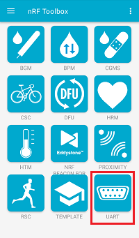
UART application in nRF Toolbox
Configure commands.
Configure the UART commands by completing the following steps:
Tap EDIT in the top right corner of the application. The button configuration window appears.
Create the active application buttons by completing the following steps:
Bind the
ncommand to one of the buttons, with EOL set to LF and an icon of your choice.Bind the
fcommand to one of the buttons, with EOL set to LF and an icon of your choice.Bind the
tcommand to one of the buttons, with EOL set to LF and an icon of your choice.Bind the
dcommand to one of the buttons, with EOL set to LF and an icon of your choice.Bind the
icommand to one of the buttons, with EOL set to LF and an icon of your choice.
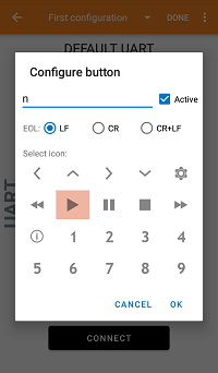
Configuring buttons in the UART application of nRF Toolbox
Tap DONE in the top right corner of the application.
Connect to the device.
Tap CONNECT and select the Zigbee_Switch device from the list of devices.
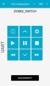
The UART application of nRF Toolbox after establishing the connection
Observe that LED 0 on the light switch node is solid.
Observe that LED 1 on the light switch node is solid.
This indicates that the Bluetooth LE connection is established.
In nRF Toolbox, tap the buttons you assigned to perform the test:
Tap the n and f command buttons to turn the LED on the Zigbee Light bulb node on and off, respectively.
Tap the t command button two times to toggle the LED on the Zigbee Light bulb node on and off.
Tap the i and d command buttons to make adjustments to the brightness level.
You can now control the devices either with the buttons on the development kits or with the NUS UART command buttons in the nRF Toolbox application.
Testing the Matter extension
See Matter extension for the runtime behavior driving the steps below.
To test the extension, you need:
A light switch built with the Matter extension (see Configuration files for sample extensions).
A Zigbee test setup to verify Zigbee operation before Matter commissioning. You can use either the standard setup (a Network coordinator and a Zigbee light bulb) or, alternatively, only a Touchlink-capable light bulb (for example, the Zigbee: Light bulb built with the Matter extension), in which case the Zigbee Coordinator is not needed.
A Matter controller that can commission a Thread device over Bluetooth LE, for example CHIP Tool or an ecosystem app (Apple Home, Google Home, Amazon Alexa).
A Thread Border Router reachable by the Matter fabric.
Optionally, a Matter light commissioned to the same Thread fabric to be bound to the light switch (for example, a Matter Light Bulb sample).
Complete the following steps to exercise the full Zigbee-to-Matter flow:
Verify Zigbee operation in one of the following ways:
Follow the standard Testing procedure with a Zigbee Network coordinator and a Zigbee light bulb.
Or, skip the Zigbee Coordinator and pair the light switch directly with a Touchlink-capable light bulb:
Power the light bulb (Touchlink target).
Power the light switch and press the Touchlink button (see Touchlink commissioning). The two devices form a distributed-security Zigbee network and the light switch finds the bulb to control, without a Zigbee Coordinator on the network.
While the device is still a Zigbee End Device, it also advertises for Matter commissioning over Bluetooth LE.
Commission the device using the onboarding payload produced by the Matter factory data build (QR code or manual pairing code). After the Matter CASE session is established, the light switch hands the radio over to Thread and stops participating in the Zigbee network.
Bind the light switch to a Matter light (for example, with
chip-tool binding write binding …) and use the dimmer button to toggle or dim the bound light over Thread.To return the device to Zigbee operation, trigger a Matter factory reset from the controller (for example,
chip-tool pairing unpair …). The device reboots as a fresh Zigbee End Device with Matter Bluetooth LE advertising active again.
Sample output
You can observe the sample logging output through a serial port after connecting with a terminal emulator (for example, nRF Connect Serial Terminal). See Testing and optimization in the nRF Connect SDK documentation for the required settings and steps.
Dependencies
This sample uses the following nRF Connect SDK libraries:
Zigbee subsystem:
zb_nrf_platform.h
It uses the ZBOSS stack:
ZBOSS Zigbee stack 4.2.2.4 (API documentation)
In addition, it uses the following Zephyr libraries:
include/zephyr.hinclude/device.h
The following dependencies are added by the multiprotocol Bluetooth LE extension:
Zephyr’s Bluetooth API:
include/bluetooth/bluetooth.hinclude/bluetooth/gatt.hinclude/bluetooth/hci.hinclude/bluetooth/uuid.hinclude/bluetooth/services/nus.h
If you are using the optional Matter extension, this sample requires the following dependencies:
The Matter stack (
CONFIG_CHIP) shipped with the nRF Connect SDK, including the Binding and Identify clusters and the Matter factory data module.OpenThread (used by Matter on 802.15.4) and the SoftDevice Controller (used for CHIPoBLE commissioning).
The
zigbee_matter_coexistenceandzigbee_matter_protocol_statelibraries, which orchestrate the 802.15.4 radio hand-over and persist the selected protocol.The
nrf_802154_callbacks_dispatcher(CONFIG_NRF_802154_CALLBACKS_DISPATCHER) with runtime re-init (CONFIG_NRF_802154_DRV_REINIT_ENABLED).