How to work with Devicetree Visual Editor
The nRF Connect for VS Code extension comes with the Devicetree Visual Editor, which provides the overview of the devicetree context and a visual representation of the devicetree file structure. It simplifies the editing process of devicetree files by reducing the time needed to manually convert a hardware schematic to devicetree language.
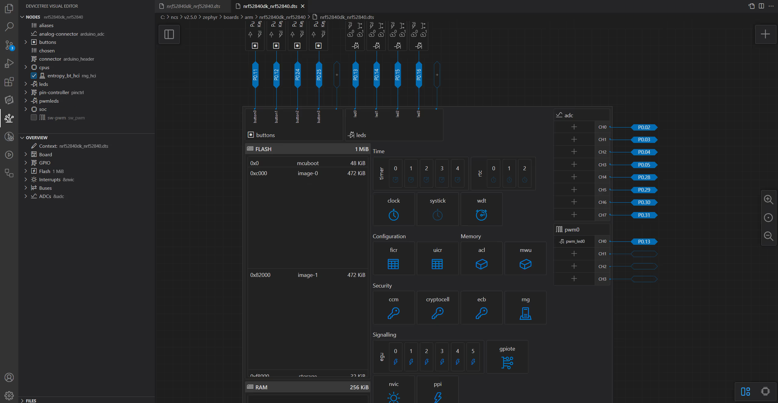
This page provides information about the most common ways you can interact with the editor. For a detailed description of all the interface options, see the Devicetree Visual Editor interface page in the UI and reference section.
Changes in the editor are propagated to the devicetree file in real time (and the other way around), and you can save your changes in either of them. This is different from the Kconfig GUI, which requires saving changes using one of the dedicated options in the GUI. If you still prefer to manually edit the devicetree files, see the How to manually edit devicetree files page.
Note
The hardware limitations for pins and nodes also apply when using the editor. For example, you can only add a number of different pins for the adc node. Other restrictions are inherited from the devicetree language and Zephyr.
How to access the Devicetree Visual Editor
You can only have one Devicetree Visual Editor instance open for each compiled devicetree output.
To open the Devicetree Visual Editor, click Devicetree in the Actions View.
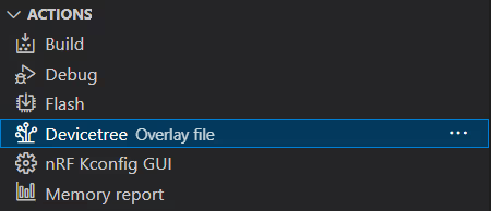
This opens the main screen of the Devicetree Visual Editor in a separate tab in the Editor.
Important
Make sure you open and edit a .dts or an .overlay file that you created. Directly editing .dts board files or .overlay files that come with the nRF Connect SDK installation may have unintended consequences to other boards or to applications that use the same board.
How to create devicetree files in the editor
The Devicetree Visual Editor is meant to be used with existing .dts and .overlay files. For this reason, it does not offer the option to create these files from scratch.
Make sure to create devicetree files before you use the editor.
How to assign nodes to pins
To assign a node to a pin, complete the following steps:
- Open the Pins view using the switch at the bottom right corner of the Editor.

- Click the pin to which you want to assign a node.
The Pin Overview panel is updated.
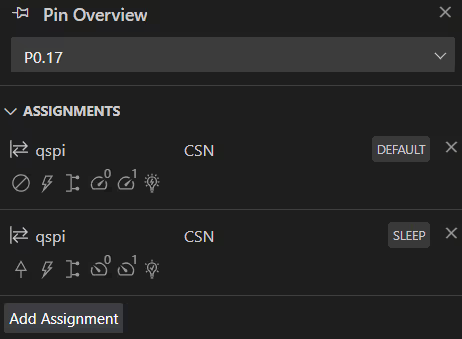
- Click the Add Assignment button.
- Select the options for the node from the available menu fields.
- Click Assign.
- Save your changes either in the editor or in the devicetree file.
The node is assigned to the chosen pin and the change is mirrored in the devicetree code file. You can hover over the pin to see the tooltip with the list of available assignments, including the respective node, function, and state.
How to assign pins to nodes
To assign a pin to a node, complete the following steps:
- Open the Peripherals view using the switch at the bottom right corner of the Editor.

- In the Nodes View, click the node you want to assign to a pin.
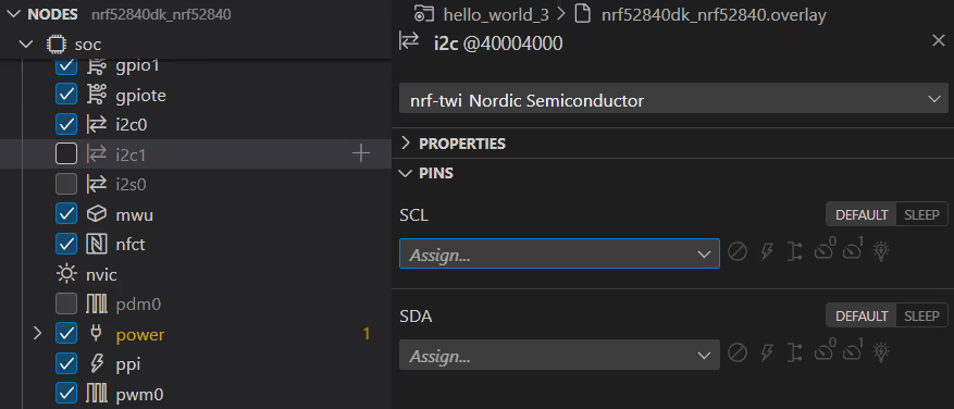
The Node Inspector panel is updated.
-
In the Pins properties, assign the node property to a pin by selecting it from the drop-down menu. The selection is mirrored in the Peripherals and Pins views.
Tip
Make sure the node you are assigning to a pin is enabled. Pin assignments to disabled nodes are hidden.
-
Save your changes either in the editor or in the devicetree file.
The node is assigned to the chosen pin and the change is mirrored in the devicetree code file. You can hover over the pin in the Pins view to see the tooltip with the list of available assignments, including the respective node, function, and state.
How to unassign nodes
To unassign a node from a pin, complete the following steps:
- Open either the Peripherals or Pins view of the editor.
- Click the pin that you want to unassign a node from. The side panel of the view displays information about the pin.
- Click Clear PIN button to the right of the pin entry (next to its state).
- Save your changes either in the editor or in the devicetree file.
The node is unassigned from the pin and the change is mirrored in the devicetree code file.
Note
If there are multiple nodes assigned to the pin, as indicated by additional chevrons next to the assigned pin entry in the Pins view, you can either unassign them one by one or unassign a specific pin.
How to add new nodes
To add a new node, complete the following steps:
-
Hover over the Nodes View area. The Add Global Node button appears at the top of the area (the plus icon).

Note
The button is only active when you have the Devicetree Visual Editor open and selected in the Editor.
-
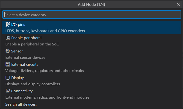
Click the Add Global Node button. The Add Node quick pick menu appears.
-
In the quick pick menu:
- Select the node category and the I/O pin. The lists are populated from the Zephyr and nRF Connect SDK devicetree type YAML files.
- Write the name of the new node. The name can only contain letters, numbers, and the following symbols:
-,@, and_. - Select the pin to which the new node is going to be assigned.
-
Save your changes either in the editor or in the devicetree file.
The node is added to the tree under the provided parent with an icon assigned automatically based on the node type.
You can also add nodes by clicking the Add Node button that appears when hovering over valid parent nodes and that is available in the top right corner of the Peripherals and Pins views.
Note
You can expand a node to see its children only if the node is enabled. For this reason, you cannot edit children of a disabled node.
How to add new properties
To add a new property, complete the following steps:
- Make sure you are in the Peripherals view.
-
Select the node in the Nodes View or directly from the Peripherals view. The view highlights the selected node and the Node Inspector panel is populated with the information about it. This panel also includes the Add Property button.

-
Click the Add Property button. A window appears.
- Select the property name and fill in or select its value.
- Click on Add. The property is added to the node, with its location defined by the property type.
- Save your changes either in the editor or in the devicetree file.
How to edit node and property values
To edit nodes or properties, complete the following steps:
- Make sure you are in the Peripherals view.
- Select the node in the Nodes View or directly from the Peripherals view. The view highlights the selected node and the Node Inspector panel is populated with the information about it.
- Update the value of the node property you want to edit. The editor fields and the devicetree code file are both updated automatically at the same time.
- Save your changes either in the editor or in the devicetree file.
Depending on the field and its type, editing node and property values can require additional steps. The following sections include examples of editing some particular node types.
How to edit GPIO pin element values
To edit GPIO pin element values, complete the following steps:
- Make sure you are in the Peripherals view.
- Select a node that can have GPIOs assigned.
For example, one of the nodes of the
buttonsorledsdrivers. -
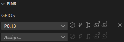
In the Node Inspector, open the Pins tab to display the information about the node.
-
Select the desired value for each of the options by clicking the icons next to the pin assignment drop-down menu. The icons change based on the selected value.
Note
Some of the options and values are interdependent. Moreover, in the nRF Connect SDK versions earlier than v1.6.0 you can only set the Active low or high flag for the pins.
-
Save your changes either in the editor or in the devicetree file.
How to remap elements
Remapping allows you to use compatible peripherals by matching the pins on peripherals to pins on Nordic boards. With devicetree, you can use so called nexus nodes, for example GPIO nexus nodes, to remap values for an Arduino shield. The editor simplifies the remapping process.
To remap elements for nodes that allow this, complete the following steps:
- Make sure you are in the Peripherals view.
-
In the Nodes View, select a node that uses properties organized into a map. The Node Inspector displays the properties of the node. For example, this can be the
arduino-header-r3node.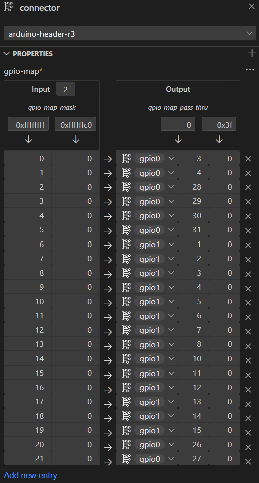
-
Edit the values in the map. If you need to add a new entry to the table, use the Add new entry action at the bottom of the table.
- Save your changes either in the editor or in the devicetree file.
How to edit partition memory ranges
To edit flash partition memory ranges, complete the following steps:
- Make sure you are in the Peripherals view.
-
Select a flash node or a partition node under the parent
soc/flash-controllernode. The Node Inspector is updated. If you selected a partition, it is also highlighted in the Peripherals view.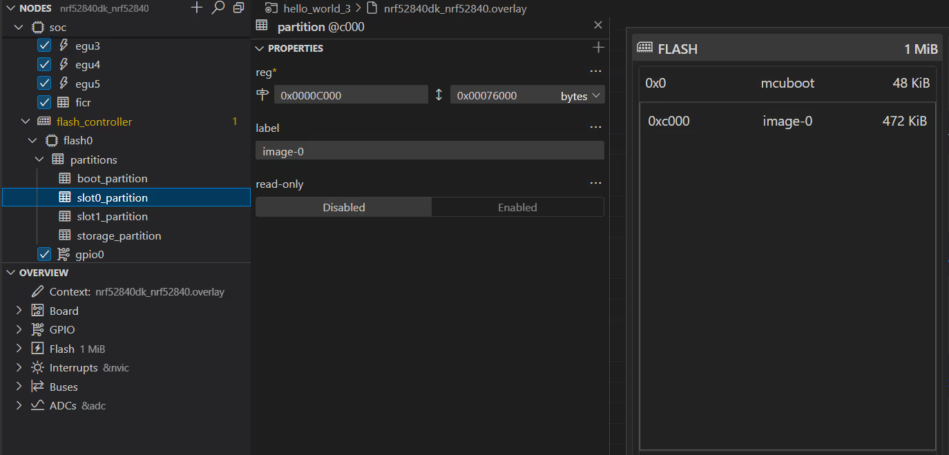
-
Edit the memory partition layout values in the Node Inspector. For example, you can change the
regregister space property, so that the partition either begins at a different address (first field) or has more memory space available (second fields), or both. Changes are automatically mirrored in the memory layout in the Peripherals view. -
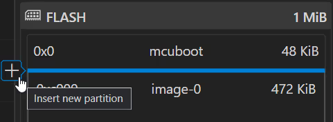
If you want to add a new partition, click the Insert new partition button in the Peripherals view. The button appears when you hover your mouse cursor between the partitions.
-
Save your changes either in the editor or in the devicetree file.
How to delete nodes
To delete any node in the Nodes View, complete the following steps:
- Right-click the node name in the tree. The context menu appears.
- Click Delete to remove the element from the tree.
- Save your changes either in the editor or in the devicetree file.
How to delete properties
To delete properties in the Node Inspector, complete the following steps:
- Make sure you are in the Peripherals view.
- Select the node in the Nodes View.
- In the Node Inspector, go to the property you want to delete.
-
Click Delete from the More actions... menu that appears after hovering over the property field.
Note
You can only delete properties that are optional.
-
Save your changes either in the editor or in the devicetree file.
How to revert changes
To revert changes, you can use the Undo action from VS Code. The Undo action is also available from the context menu in the Peripherals and Pins views, the Nodes View, and the Node Inspector.