How to manually edit devicetree files
If you want to manually edit the devicetree files directly in the Editor instead of using the Devicetree Visual Editor, you can follow the steps described below and take advantage of the Devicetree language support.
Important
Make sure to create an overlay file in case you need one before you start editing it.
Directly editing .dts or .overlay files that come with the nRF Connect SDK installation may have unintended consequences to other boards or to applications that use the same board.
How to add a node in overlay files
Complete the following steps:
- Open the
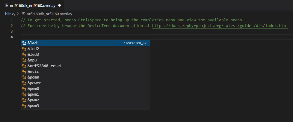
.overlayfile you want to edit. - Press Ctrl-Space to start the autocompletion feature. A list of the available nodes appears.
- Click the name of the node to complete the autocompletion.

For detailed information about writing property values, see Zephyr's documentation.
Example: Adding a dimmable LED
In this example, you will add a dimmable LED to the board.
Zephyr provides a generic binding for PWM LED controllers, named pwm-leds. Bindings are type definitions for devicetree nodes, defining which properties the node supports and what values they expect.
Bindings are specified by setting the compatible property within the node where they are supposed to be used, which in this example is the PWM LED controller node (pwmleds). In this pwmleds controller node, you can add nodes for each LED. The pwm-leds binding defines the properties of its child nodes as well, so the properties for LED nodes led_pwm_1 and led_pwm_2 can also be auto-completed.
Complete the following steps:
- Add the controller node
pwmledsunder the root node in devicetree. - Add the
pwm-ledsbinding for the driver to pick up. - Add LEDs as child nodes on the
pwmledscontroller node, withpwmsandlabelproperties. -
Make sure the
pwmsproperty of thephandle-arraytype points to a PWM instance. The PWM instance takes the pin number as its only parameter. The following code example uses pins 6 and 7 on the GPIO port 0 (&pwm0):Dimmable LEDs in .dts - steps 1 to 4/ { // Devicetree root // ... pwmleds { // Controller node compatible = "pwm-leds"; // Compatible binding led_pwm_1 { pwms = <&pwm0 6>; // Pin assigned to GPIO port 0 for the LED 1 label = "PWM LED 1"; }; led_pwm_2 { pwms = <&pwm0 7>; // Pin assigned to GPIO port 0 for the LED 2 label = "PWM LED 2"; }; }; }; -
Enable the referenced PWM0 node by setting
status = "okay"and configuring the node's channels. For this, you can use the&pwm0node label reference on the root of the file:Dimmable LEDs in .dts - step 5 (Enabling PWM0)&pwm0 { status = "okay"; // Status ch0-pin = <6>; // Pin assignment for channel 0 ch1-pin = <7>; // Pin assignment for channel 1 }; -
Enable the LED PWM driver in Kconfig by adding
CONFIG_LED_PWM=yin the board'sprj.conffile.
How to add missing required properties
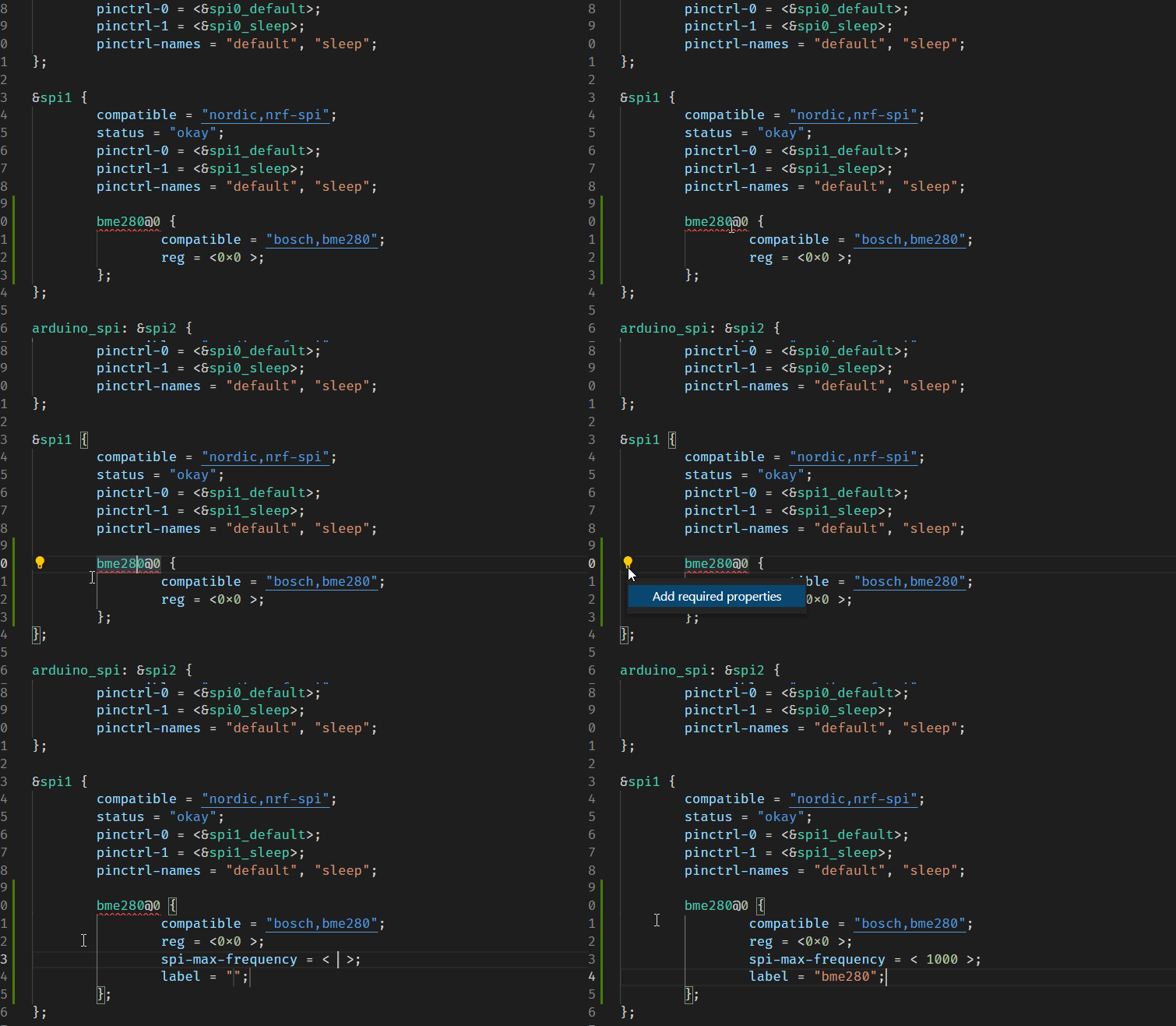
The extension includes a code action to add all required properties missing from a devicetree node. When applicable, a button with a light bulb icon appears next to the selected node in the Editor.
To add the missing required property:
- Click on the property icon.
- Click on Add required properties.
See the following GIF for a preview of these steps.

How to copy C identifiers
You can copy references to a node or property from a devicetree file and paste them into your C code.
Copying from a devicetree file
To copy C identifiers directly from a devicetree file:
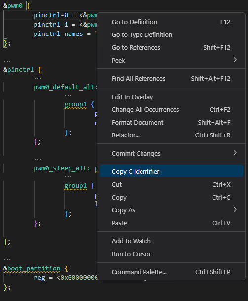
- Select the string in the file.
-
Right-click the string label.
The context menu appears.
-
Click Copy C Identifier.
If the selected symbol has a corresponding C macro, like DT_PROP(DT_NODELABEL(adc), label), it will be copied to the clipboard. A message shows up in the Status Bar with the copied string.

Copying C identifier of a node
To copy the C identifier of a node:
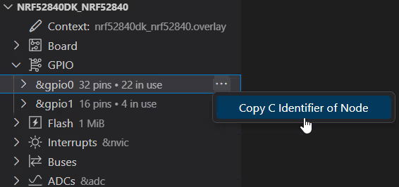
- Expand the appropriate section in the Overview of the Devicetree Visual Editor.
- Hover your mouse over the node you want to copy.
- Click on the More actions... menu icon.
- Click on Copy C Identifier of Node.
